About Me

Hi, I'm Liam Streleckis — a 4th year mechanical engineering student at Georgia Tech. I am passionate about testing, designing, and improving products to solve real-world problems. This site is a collection of projects I've worked on throughout my studies and career so far.

Resume

Download or view my resume below.

View Resume (PDF)

Projects

Applied Structural Analysis

This is a collection of tests I conducted at the Georgia Institute of Technology Structures Lab. These tests provided me with valuable experience in visualizing and analyzing structural behavior, as well as hands-on experience with testing equipment and data collection.

This is a video of a ballistics projectile test into enhanced cross laminated timber.
Applied Structural Analysis photo 1
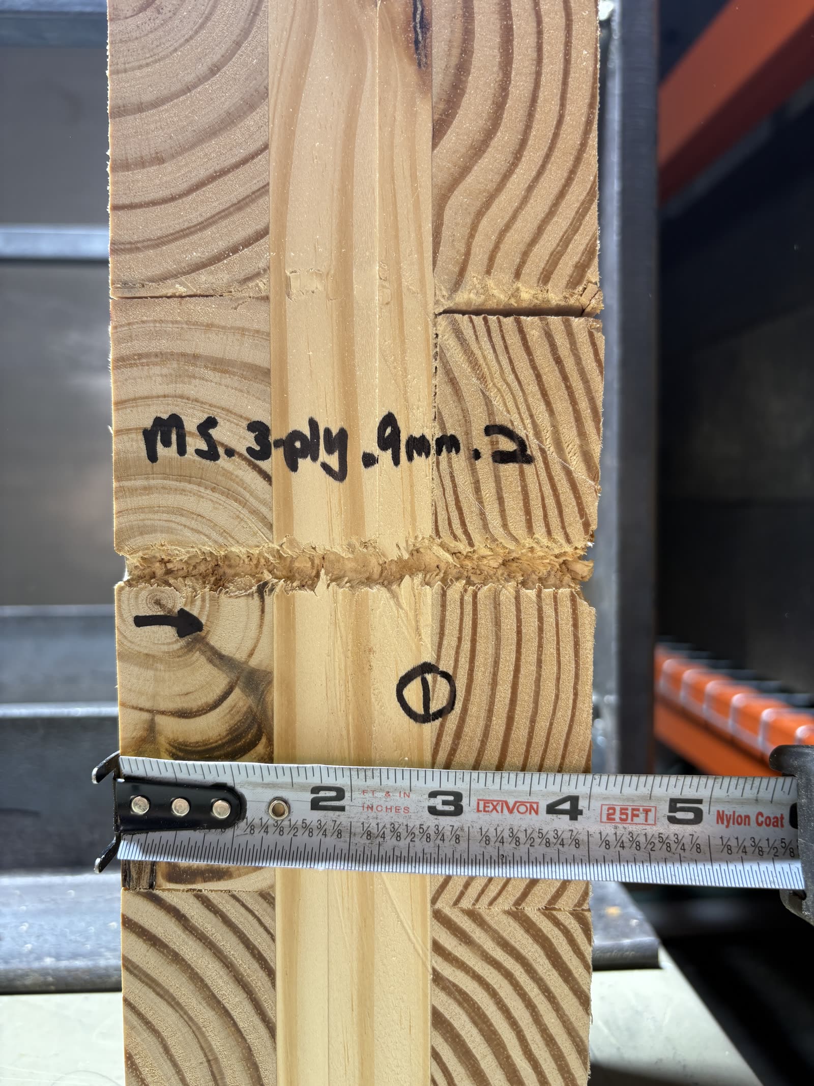
A photo of enhanced cross laminated timber post impact.
Applied Structural Analysis photo 2
An analysis image of the cross section of a projectile path post impact.
Applied Structural Analysis photo 4
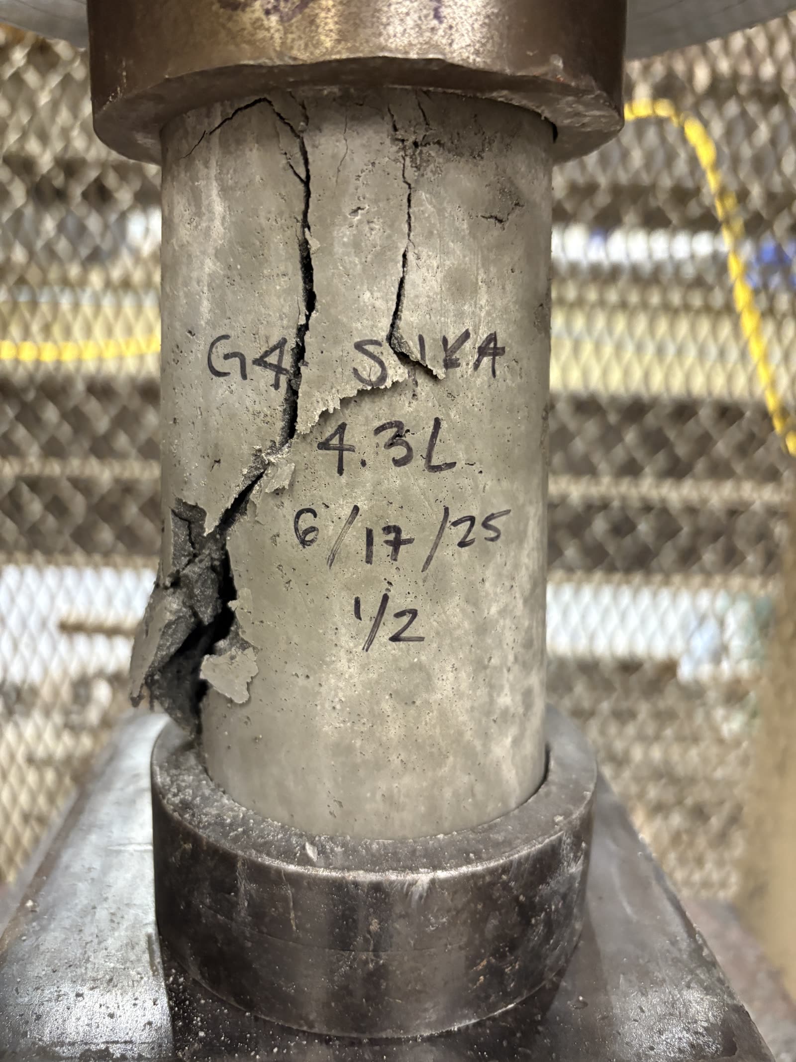
A concrete cylinder test specimen after stress testing in a universal testing machine.
Applied Structural Analysis photo 5
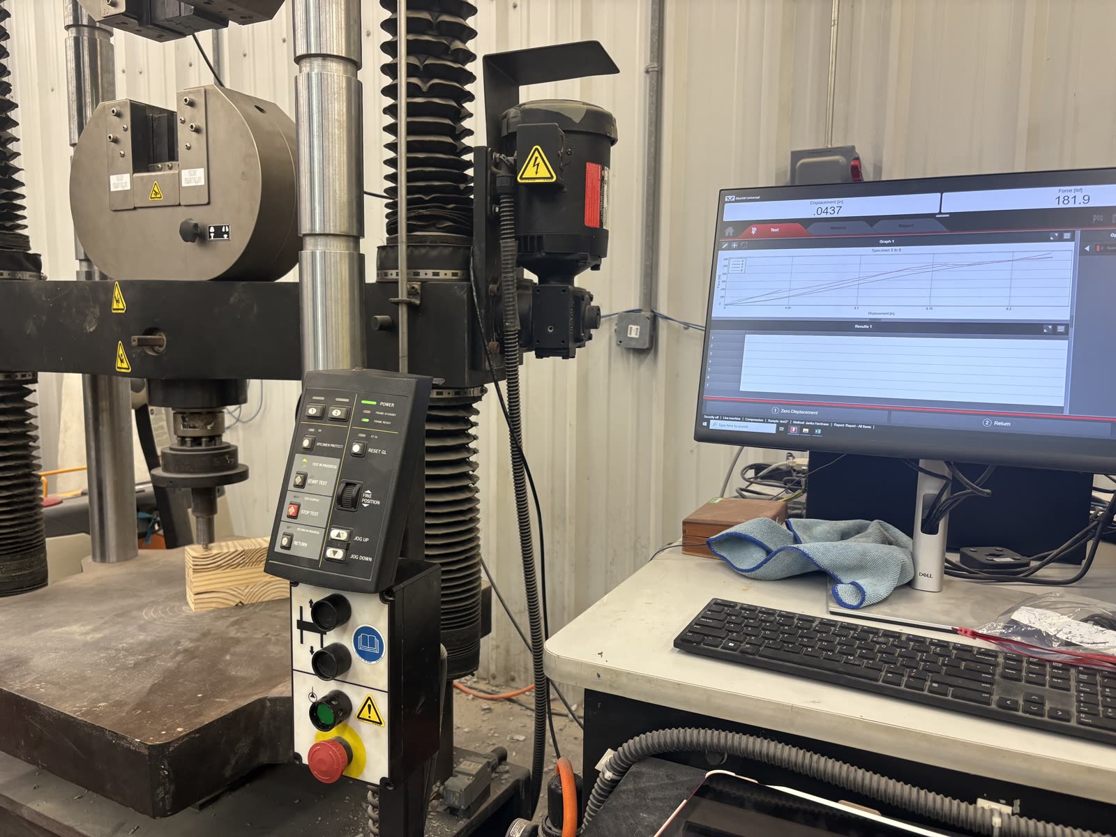
Test setup for performing Janka hardness tests on CLT.
Applied Structural Analysis photo 6
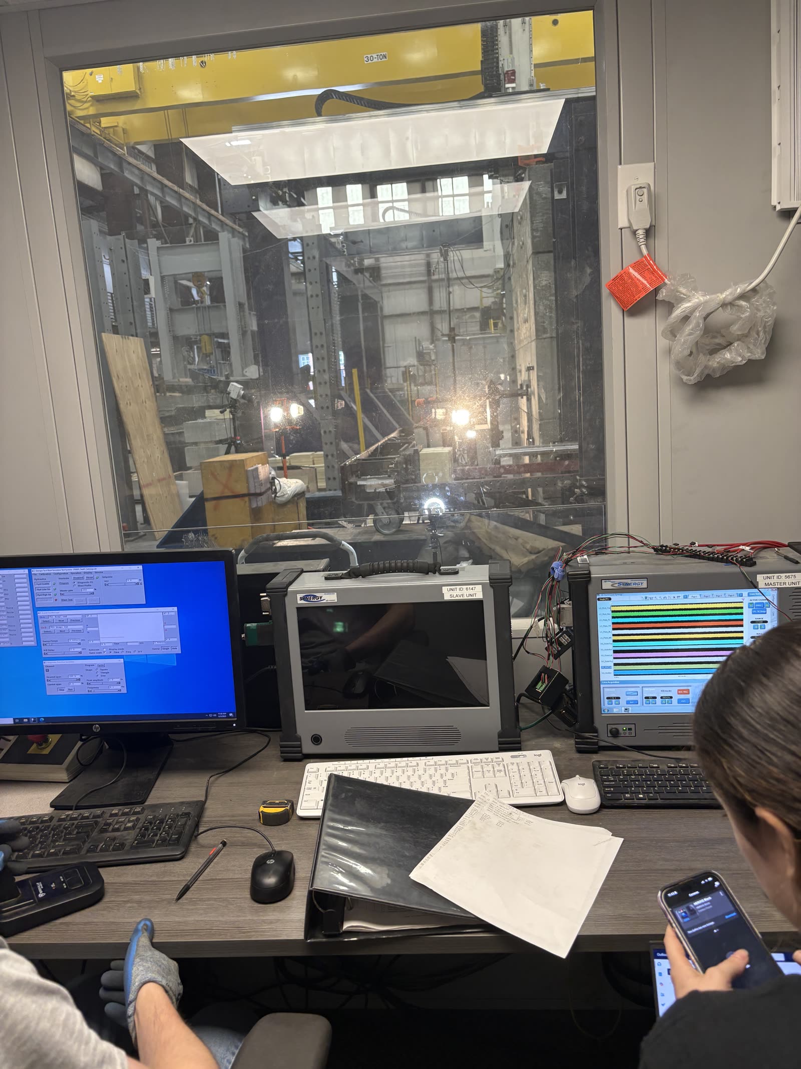
Testing setup for blast impact testing on concrete beams with varying rebar structures.
Applied Structural Analysis photo 8
Strain gauge of a concrete beam during load testing.

Water Recirculation Test Rig

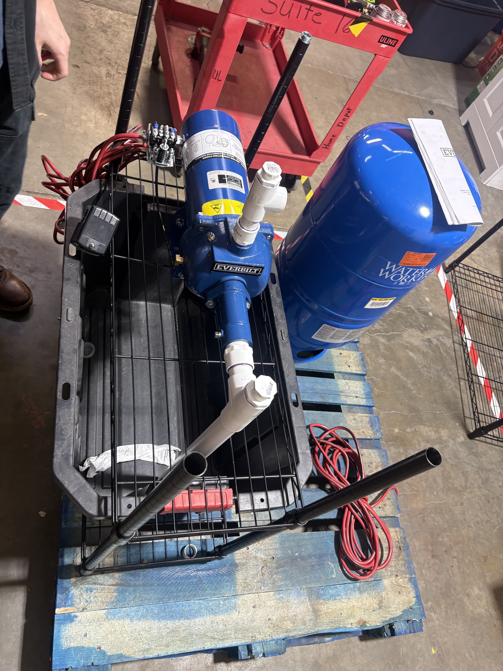
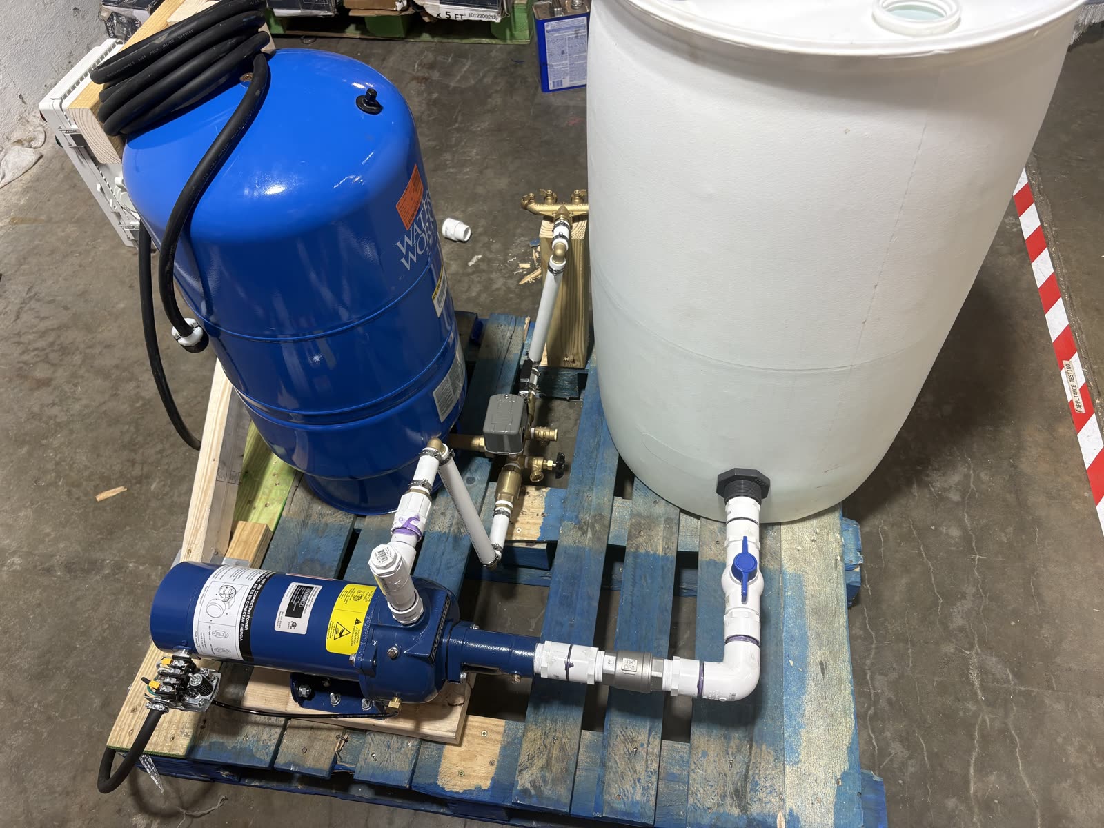
While at UL Solutions, I aided in the design and prototyping of a pressurized water recirculation test rig that expanded the laboratory's testing capabilities. This project made use of a jet pump and diapragm tank, with a pressure switch that automatically turned the pump on and off to maintain a set pressure range to mimic household water pressures. This fixture was used to test the performance of hot water recirculation pumps and will be used to test future household plumbing products in the RTL's near future.

Pressurized Water Recirculation photo 1
Initial design of system.
Pressurized Water Recirculation photo 2
Finalized system design.

Tensile Test Rig Analysis

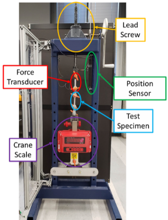
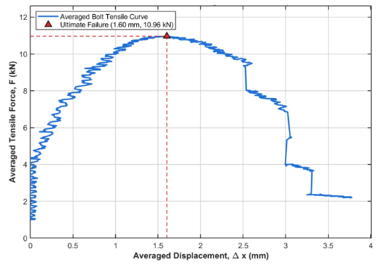
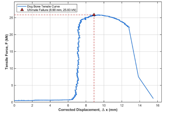
A team of students and I evaluated a custom tensile test rig for a client to determine its usable force and displacement range. We calibrated the force and position transducers, characterized the rig's own deformation under load, and tensile tested a climbing sling, a set of bolts, and an aluminum dog bone to failure. The rig met the client's 10% uncertainty requirement for forces above 1770 N and displacements above 3.83 mm, but could not reliably test the stiffer bolts, so we recommended a higher-resolution position sensor for future testing.

Tensile Test Rig Analysis photo 1
The custom tensile test rig used for calibration and specimen testing.
Tensile Test Rig Analysis photo 2
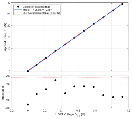
Force transducer calibration curve with a ±177 N uncertainty, setting the rig's minimum reliable force reading at 1770 N.
Tensile Test Rig Analysis photo 3
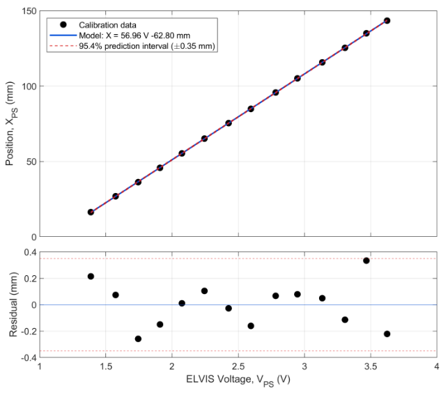
Position sensor calibration curve with a ±0.35 mm uncertainty, setting the rig's minimum reliable displacement reading at 3.5 mm.
Tensile Test Rig Analysis photo 4
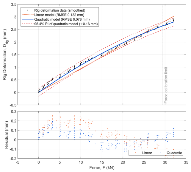
Quadratic fit of the rig's own deformation under load, used to correct specimen displacement measurements.
Tensile Test Rig Analysis photo 5
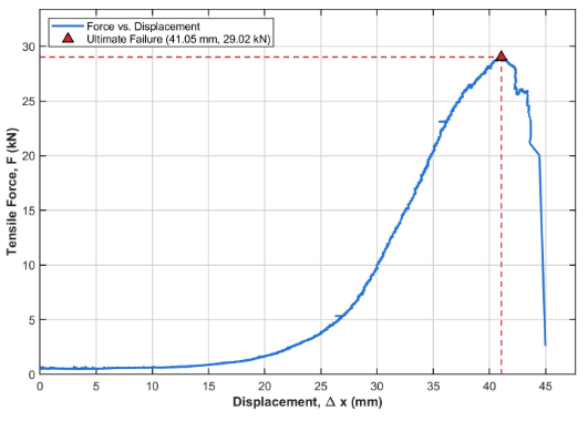
Climbing sling tested to failure at 29.0 kN and 41.1 mm of displacement, within the rig's 10% uncertainty requirement.
Tensile Test Rig Analysis photo 6
Average of five bolt tests, failing at 11.0 kN and only 1.60 mm of displacement, too small for the rig to measure within 10% uncertainty.
Tensile Test Rig Analysis photo 7
Aluminum dog bone tested to failure at 25.8 kN and 8.90 mm of displacement, within the rig's 10% uncertainty requirement.

Wing Spar Vibration Analysis

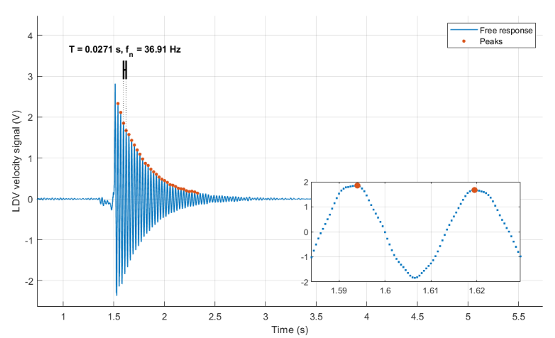
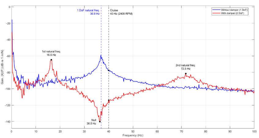
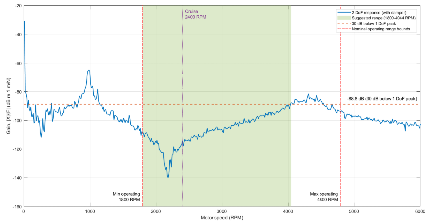
A team of students and I investigated why a client's wing spar failed near its cruise speed by modeling it as a cantilever beam and performing vibration testing. We found the spar's natural frequency, 36.9 Hz, was dangerously close to the 40 Hz cruise frequency, explaining the failure. We then designed and tested a tuned mass absorber that reduced the displacement response by 37 dB at cruise speed, and recommended operating the modified wing between 1800 and 4044 RPM to maintain a safe vibration margin.

Wing Spar Vibration Analysis photo 1
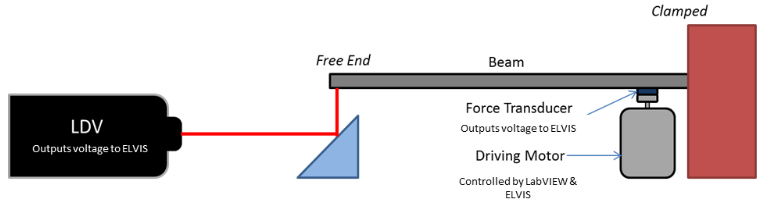
Cantilever beam test setup for the wing spar, using a shaker, force transducer, and laser doppler vibrometer (LDV) to measure response.
Wing Spar Vibration Analysis photo 2
Free vibration response of the unmodified spar, showing a measured natural frequency of 36.9 Hz.
Wing Spar Vibration Analysis photo 3
Frequency response of the spar with and without the tuned mass absorber, showing the shifted natural frequencies and null point.
Wing Spar Vibration Analysis photo 4
Recommended motor operating range of 1800-4044 RPM, where the modified spar's response stays at least 30 dB below the original peak.

SONAR Accuracy Analysis

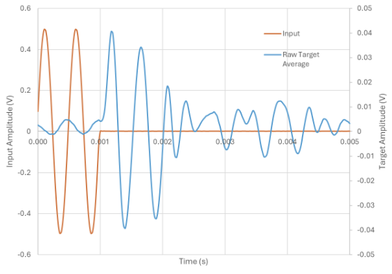
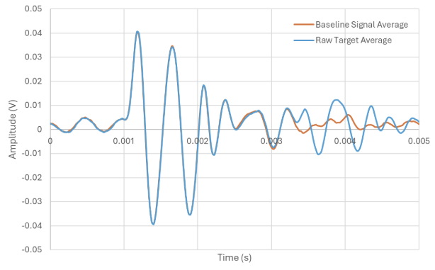
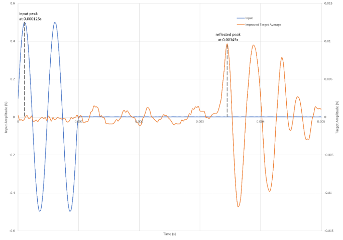
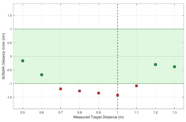
A team of students and I tested a custom SONAR distance-measurement system against a client's ±1 cm accuracy requirement. We developed a signal processing procedure that averaged multiple bursts, subtracted a target-free baseline signal, and corrected for timing bias to isolate the true reflection signal from background noise. Despite these improvements, the system averaged a -1.02 cm error across the 0-1 m target range, meeting the required accuracy only between 0.5-0.6 m and 1.2-1.3 m.

SONAR Accuracy Analysis photo 1
Raw input and target signals with a target at 70 cm; the reflected signal is buried in noise and not identifiable.
SONAR Accuracy Analysis photo 2
Raw target signal overlaid with a target-free baseline signal, used to isolate systematic noise.
SONAR Accuracy Analysis photo 3
Target signal after baseline subtraction, with input and reflection peaks now clearly identifiable.
SONAR Accuracy Analysis photo 4
Measured SONAR distance error across the test range; only points within the green band meet the ±1 cm accuracy requirement.

Stairs Manufacturing

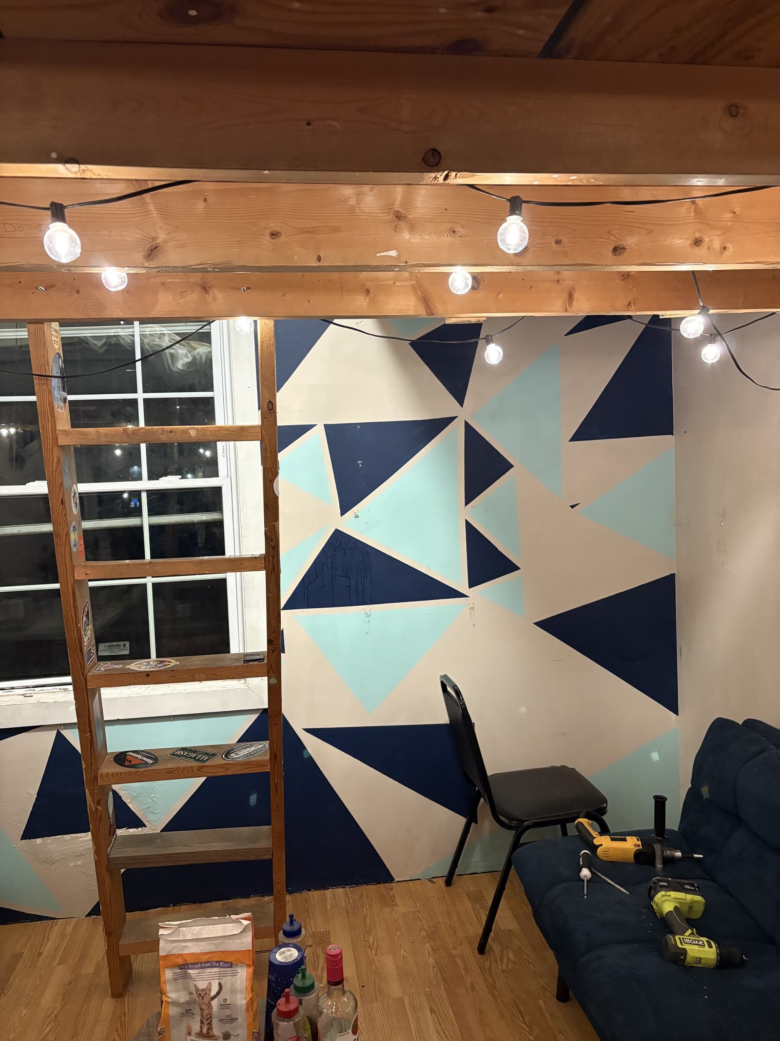
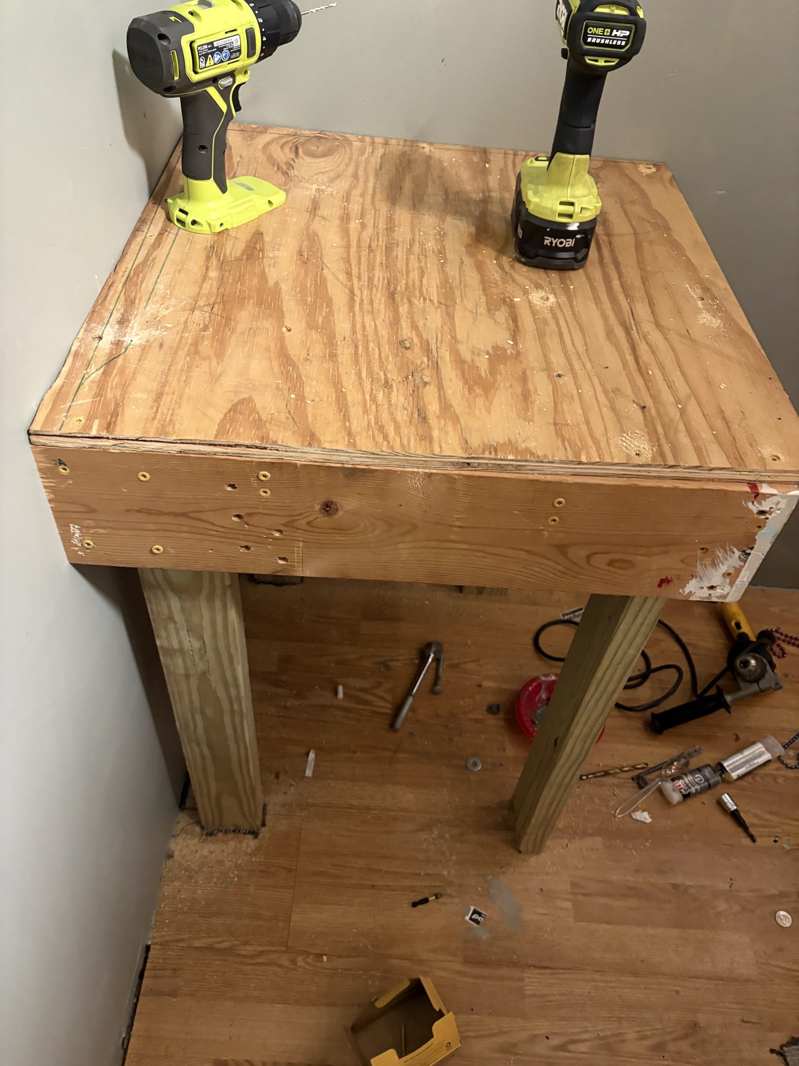
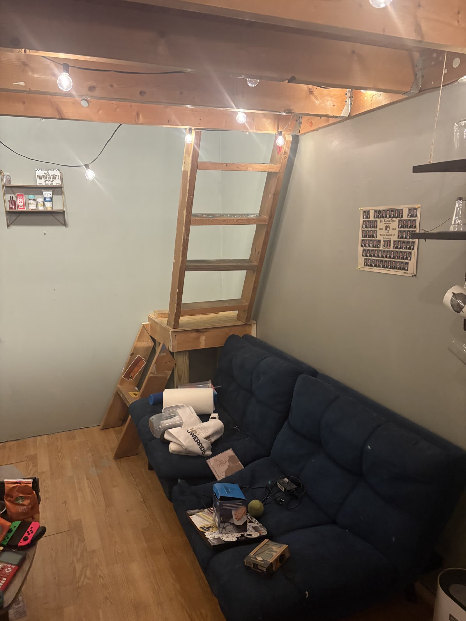
The failure of my ladder in the personal room presented me the opportunity to design and build a custom staircase for my room, allowing my cat to safely navigate to my loft. This experience developed my woodworking and design skills.

Stairs Manufacturing photo 1
Initial State of Room with Broken Ladder Step.
Stairs Manufacturing photo 3
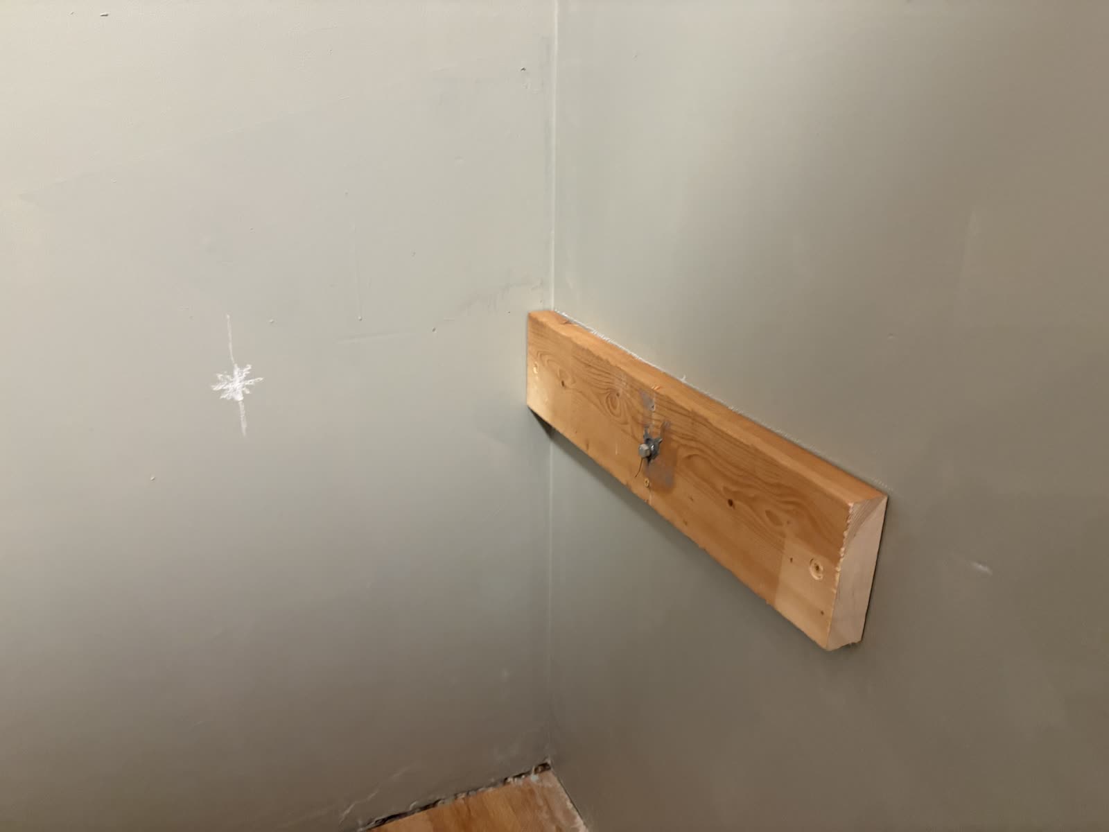
Support Structure for Stair Platform.
Stairs Manufacturing photo 4
Installed Stair Platform.
Stairs Manufacturing photo 5
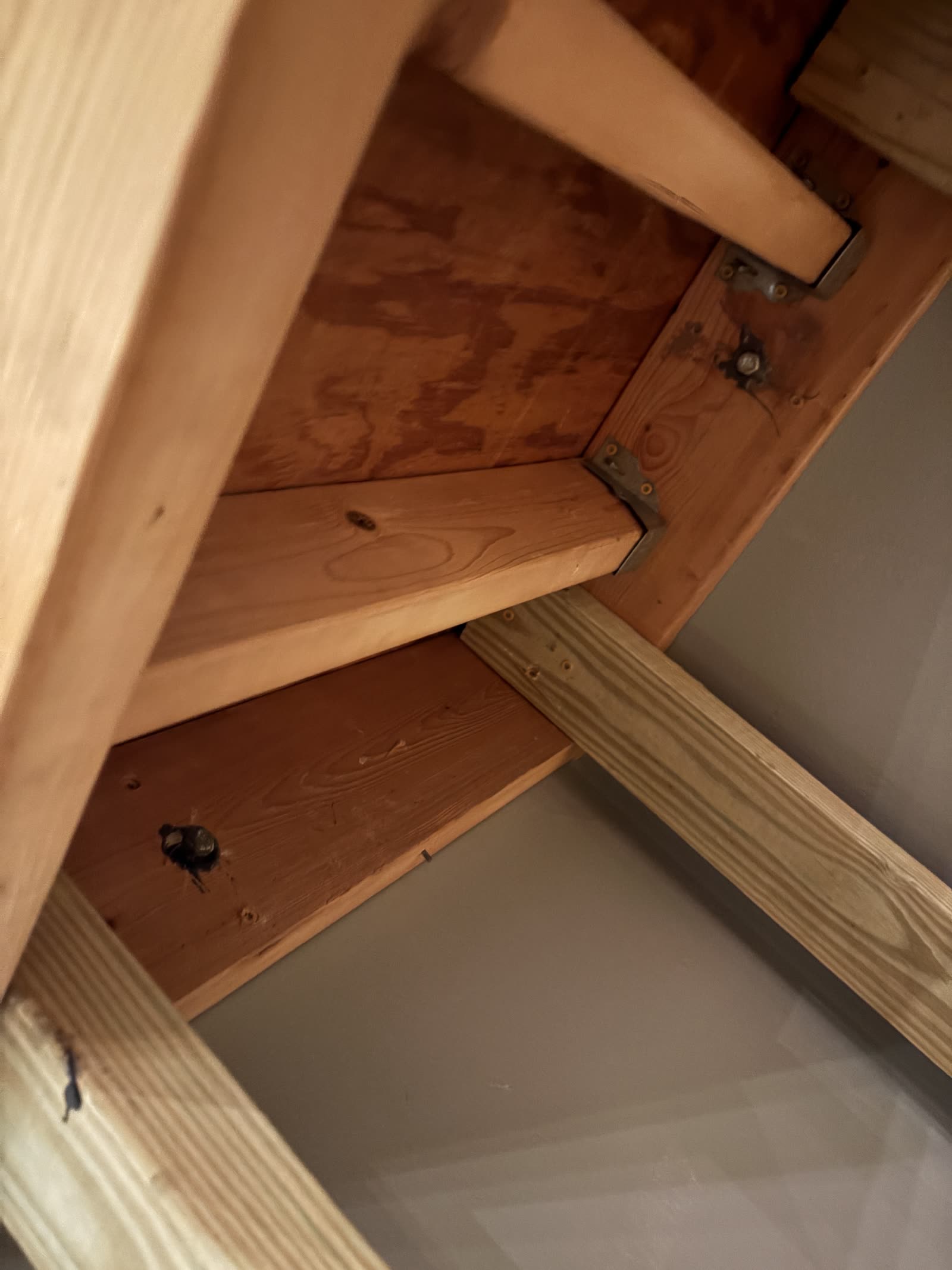
Stair Platform Underside.
Stairs Manufacturing photo 6
Final Assembly.

Samflax Interview

A team of students and I conducted an interview with Samflax, a locally owned art business, in the Atlanta area, to explore potential issues and motivations behind their business operations. This information was used to explore potential design solutions to improve business operations.

Compressed Interview with Samflax Manager.
Samflax Interview photo 1
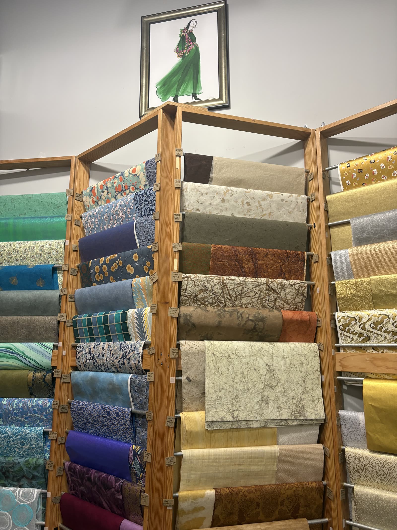
Samflax Tapestry Selection.
Samflax Interview photo 2
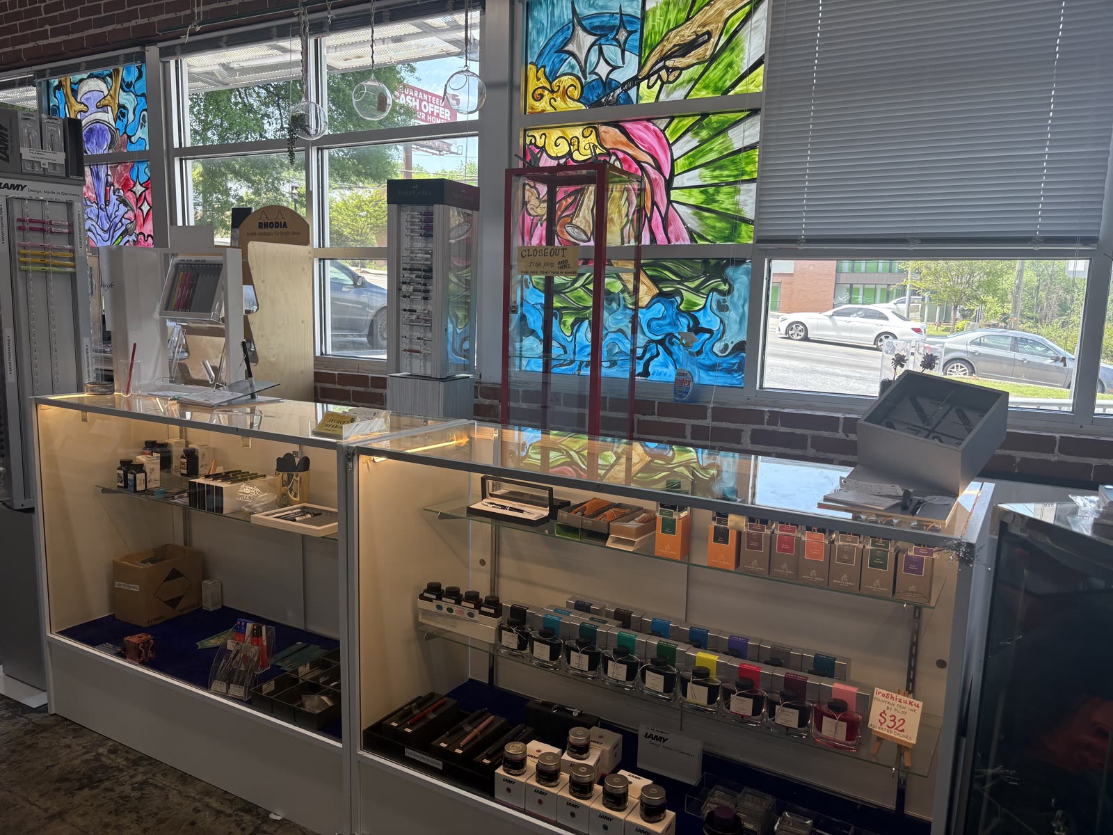
Samflax Ink & Notebook Selection.
Samflax Interview photo 3
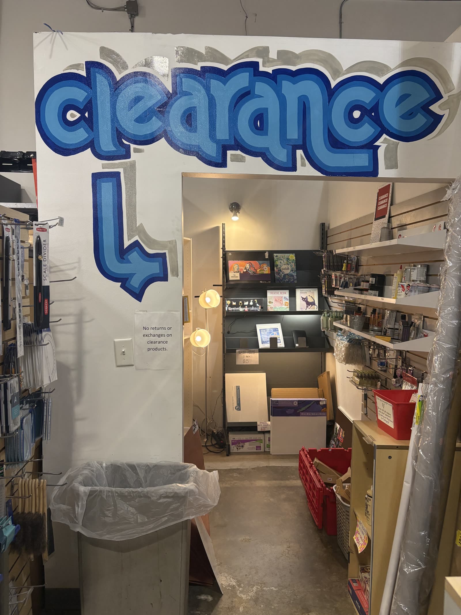
Store Room Design.
Samflax Interview photo 4
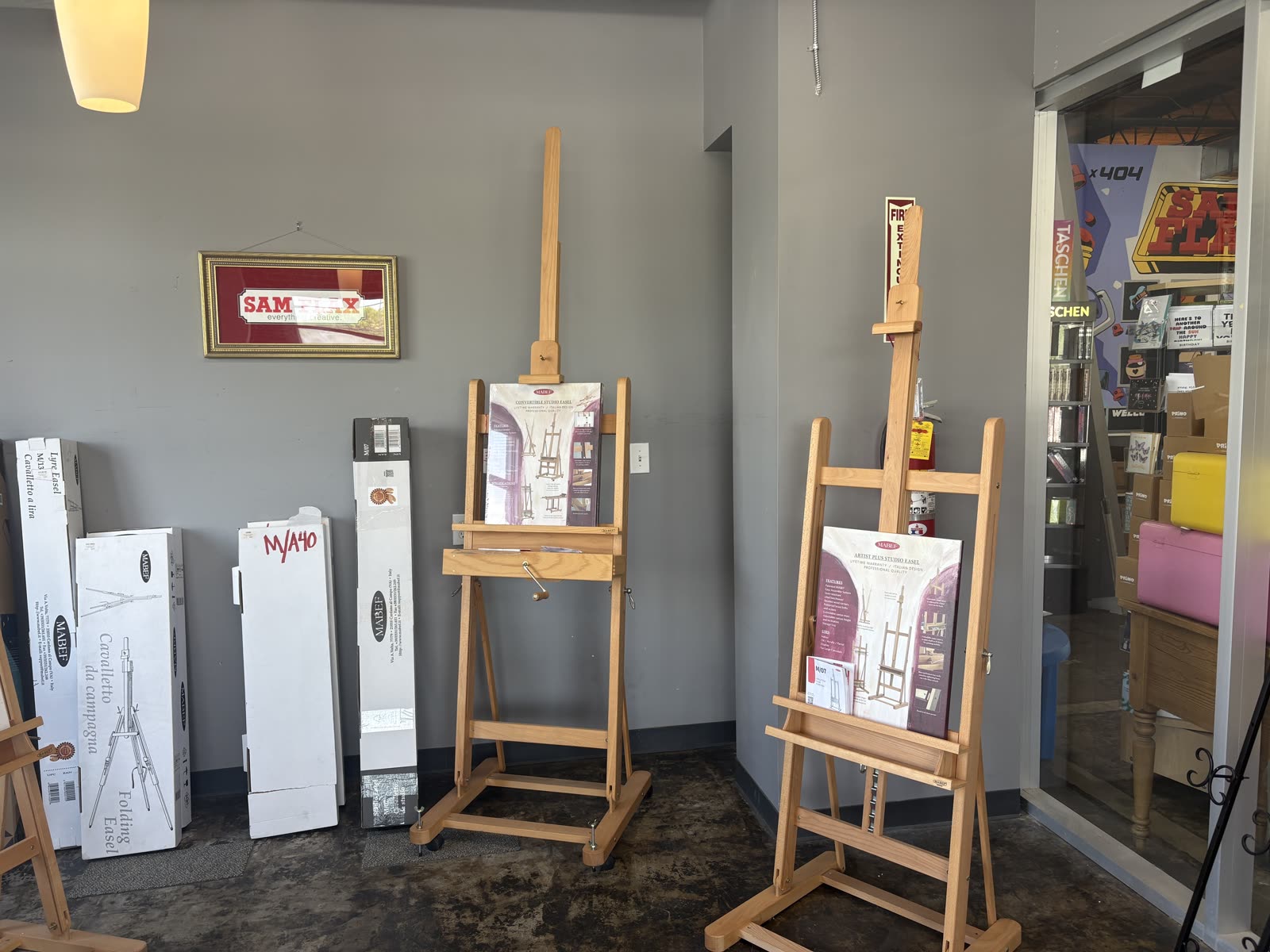
Samflax Product Display.
Samflax Interview photo 5
Samflax Customer Artwork.

Art Projects

Personal art pieces for practice and communication of ideas.
Art Projects photo 1
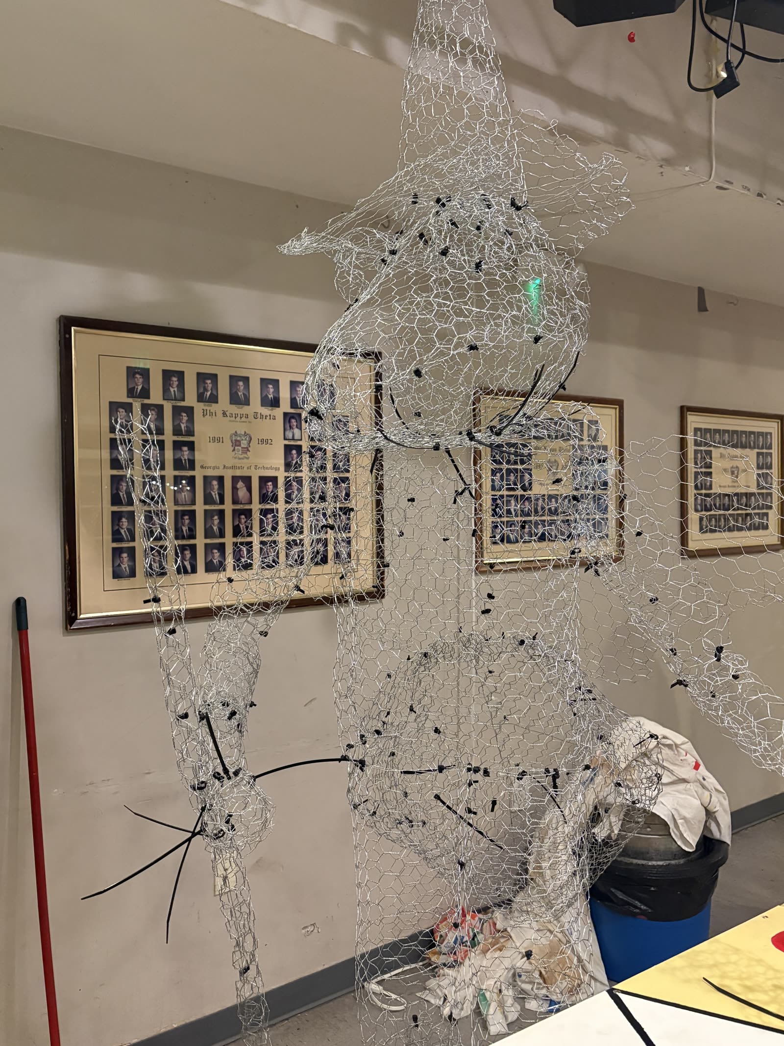
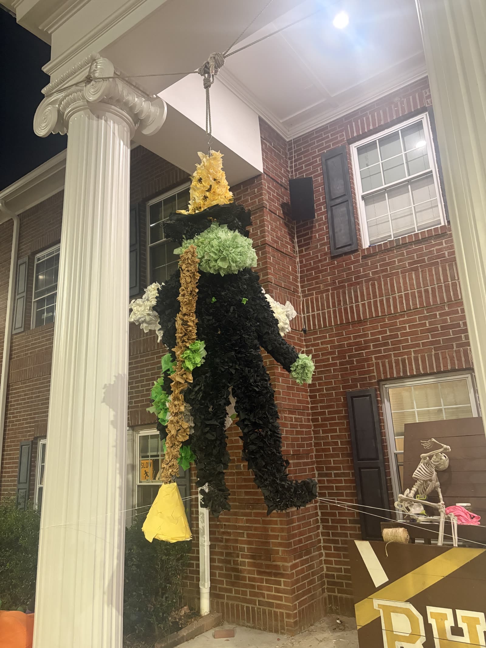
Frame of a Buzz Sculpture made for Greek Week.
Art Projects photo 3
Final Buzz Sculpture for Greek Week.
Art Projects photo 2
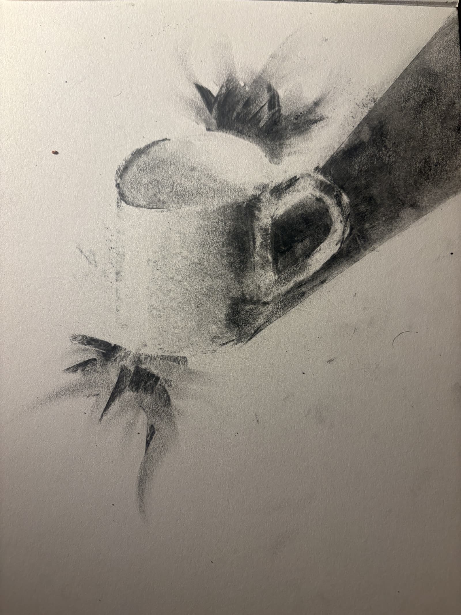
Quick Charcoal Sketch of Mug.
Art Projects photo 4
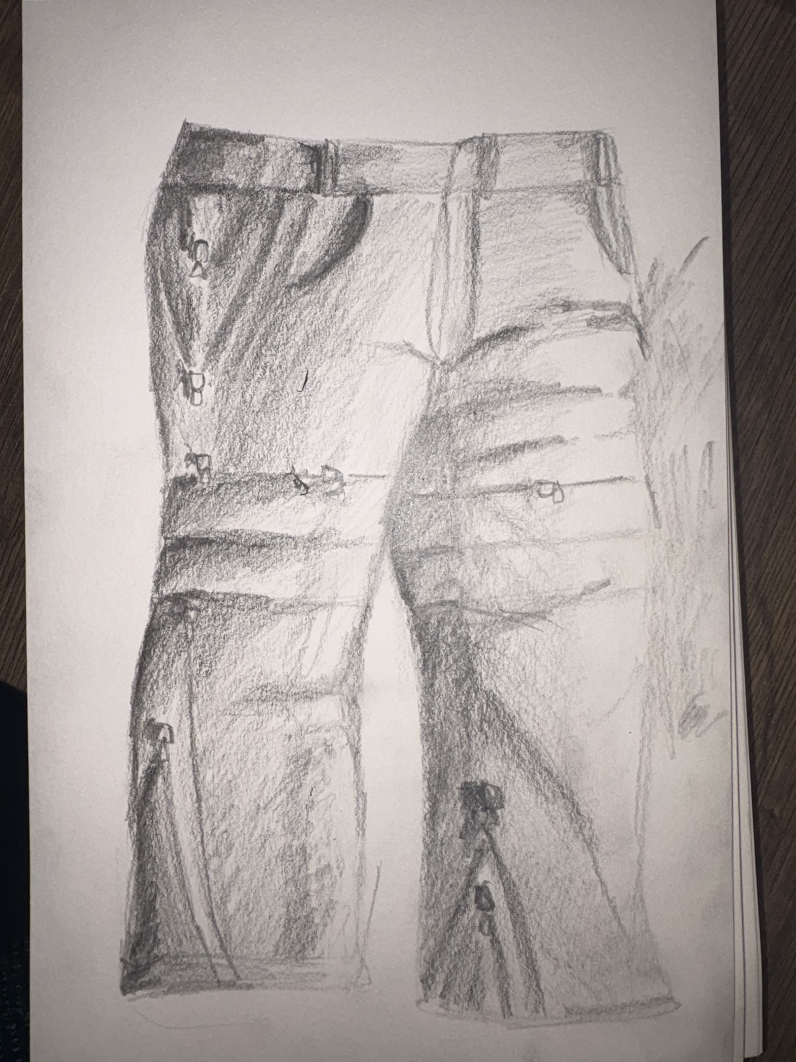
Design and sketch for Size Adjustable Pants.
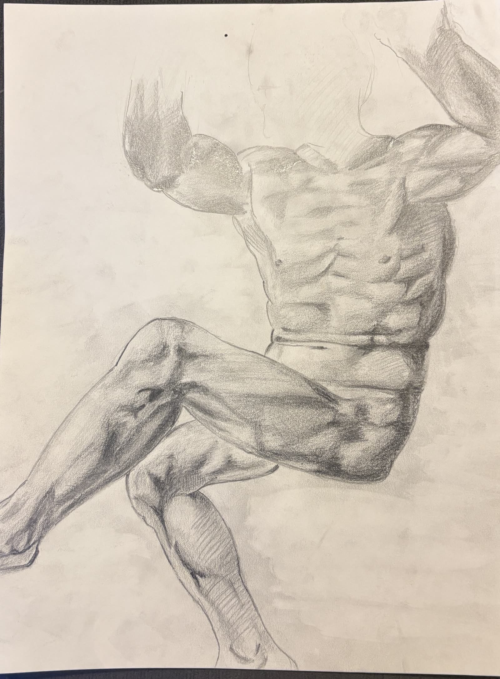
Art Projects photo 5
Pencil Recreation of a Michelangelo Sketch.
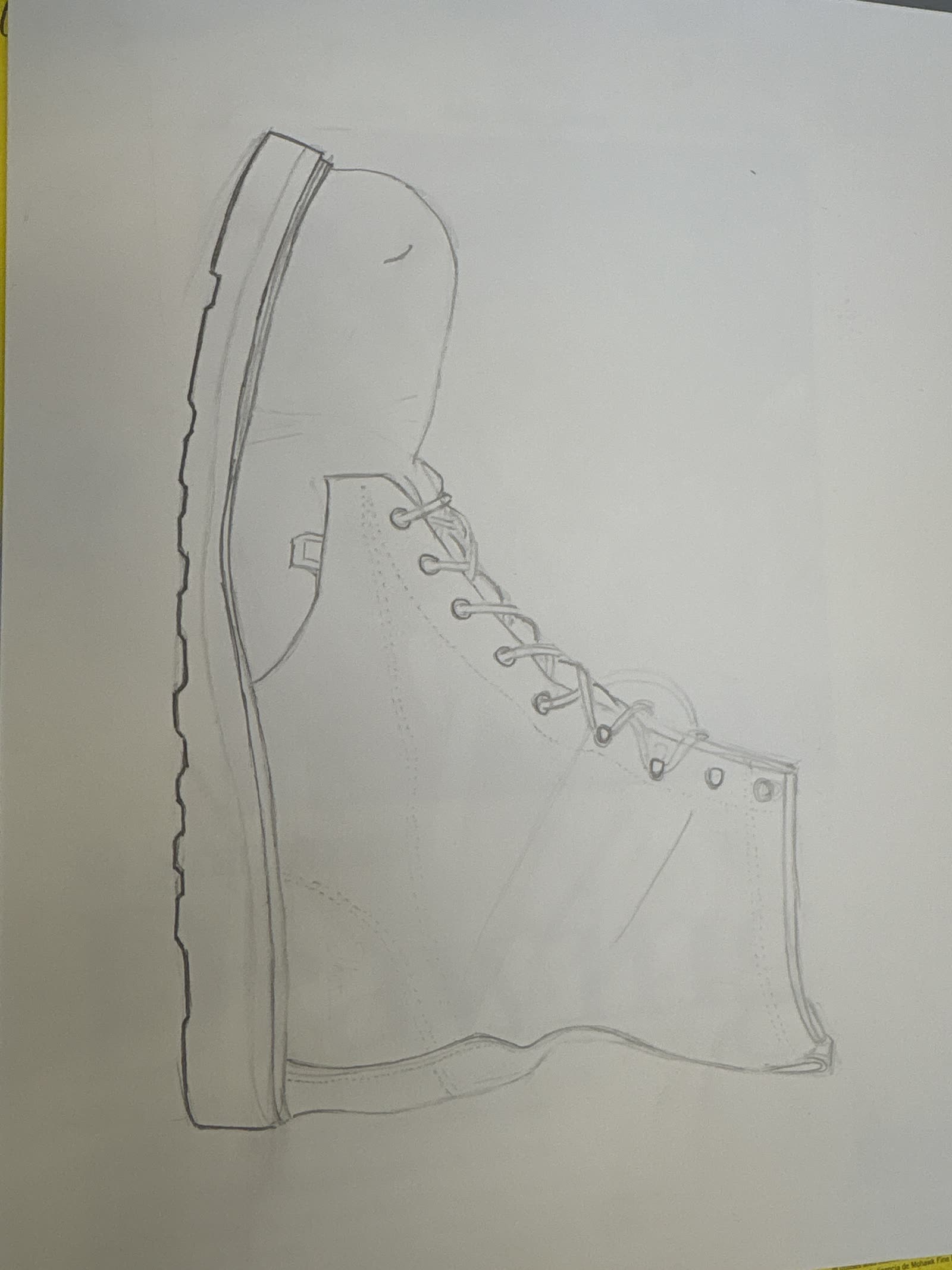
Art Projects photo 6
Linework of a Work Boot.

LinkedIn

Connect with me on LinkedIn

Email

lstreleckis3@gatech.edu